
From jestoph’s tech blog · Jestoph · · 3 min
Reverse Engineering a Microchip Design from Scratch
How an engineer reverse-engineered a raw ASIC GDS layout file using graph algorithms and constraint solvers to extract a secret message.
In brief
How an engineer reverse-engineered a raw ASIC GDS layout file using graph algorithms and constraint solvers to extract a secret message. When forward brute-forcing complex logic systems is impossible, converting hardware clock cycles into backward recurrence relations and feeding them to an SMT constraint solver can…
The Jane Street ASIC puzzle
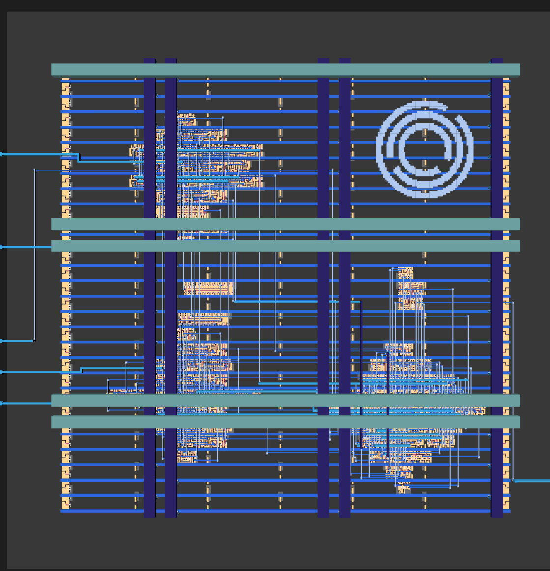
Jane Street released a reverse-engineering puzzle challenging participants to work out what a secret microchip does from raw fabrication layout files.
“The challenge is to take an ASIC and work out what it does.”
Decoding raw layout files
Inspecting the design layout files using Python's gdstk library revealed 27 logic cell elements defined by standard open-source sky130 logic gates.
“It tell me that there’s 27 elements on the warmup puzzle. A good start!”
Finding hidden circuit messages
Inspecting an included simulation trace file revealed embedded ASCII text that printed failure responses like 'TRY AGAIN' when executed.
“I play around with it, writing a small C program, and get the output ‘TRY AGAIN’.”
Down a rabbit hole of custom tools
Days were wasted building a custom SQLite circuit simulator, a new hardware description language parser, and a custom viewer before abandoning them.
“I realised I’m down too many tangents and it’s time to drop all of the custom software.”
Annotating the physical layers
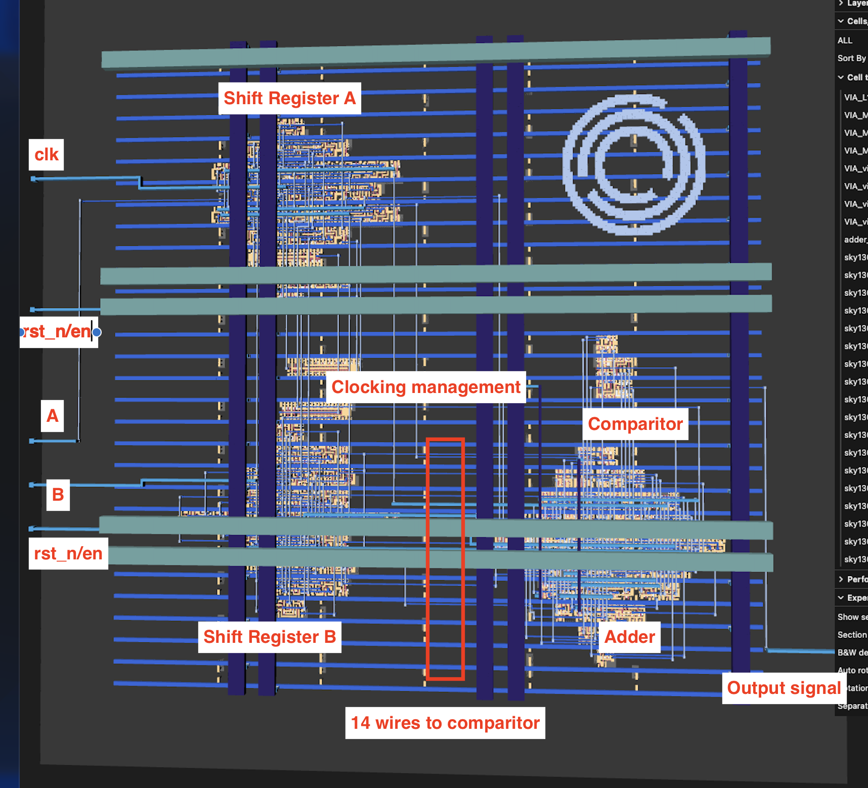
Opening the layout in a dedicated GDS viewer allowed manual mapping of inputs, outputs, and power lines by visually tracing physical paths.
Standard chip fabrication layers
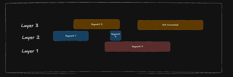
The files represent standard silicon manufacturing layers, functioning like standardized multi-material 3D print instructions.
Extracting geometry to circuit pins
Checking for 2D polygon overlaps between text labels and layer shapes extracted exact pin positions directly from the physical geometry.
“Using the information from the docs and the labels from the SVG I can now theoretically map specific geometry to the I/O of the circuit elements”
Building a connectivity graph
Merging overlapping wire segments across adjacent physical layers transformed thousands of raw polygons into a clean component netlist.
Reconstructing hardware logic
Converting the extracted netlist into Verilog code enabled digital logic simulations to test signal flow and trace hardware behavior pin by pin.
“I’ve started to be able to turn my network in to real descriptions of hardware in a language called ‘Verilog’”
Visualizing netlist logic manually
Tracing extracted connections by hand in Excalidraw helped isolate the warmup components: two shift registers, an adder, and a comparator.
Trial and error on shift registers
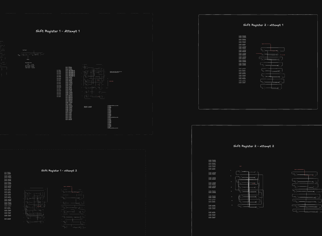
Solving the warmup circuit required finding the exact bit sequence that caused the shift register inputs to sum to 496 on the comparator.
Scaling up to the main puzzle
The main puzzle multiplied complexity dramatically, scaling from 20 cell types and 1,000 components to over 80 cell types and nearly 10,000 components.
“The real puzzle has many more component types (81 vs 20 or so) and many more of them (almost 10k vs 1k)”
Finding a real ASIC design flaw
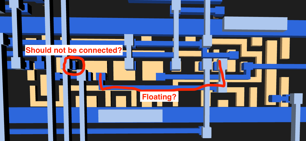
Validation checks flagged an un-driven floating wire connected only to input pins, pointing to an unexpected bug in the official puzzle design.
“I found in one section of my simulation that I had an undriven wire, meaning that its value was completely unknown to my simulator.”
Confirmation from the chip designers

Submitting a bug report to Jane Street earned email confirmation that a real flaw existed in the layout, though it did not disrupt the answer.
“The next day I had an email confirming that I was right!”
Mapping high-level subcircuits
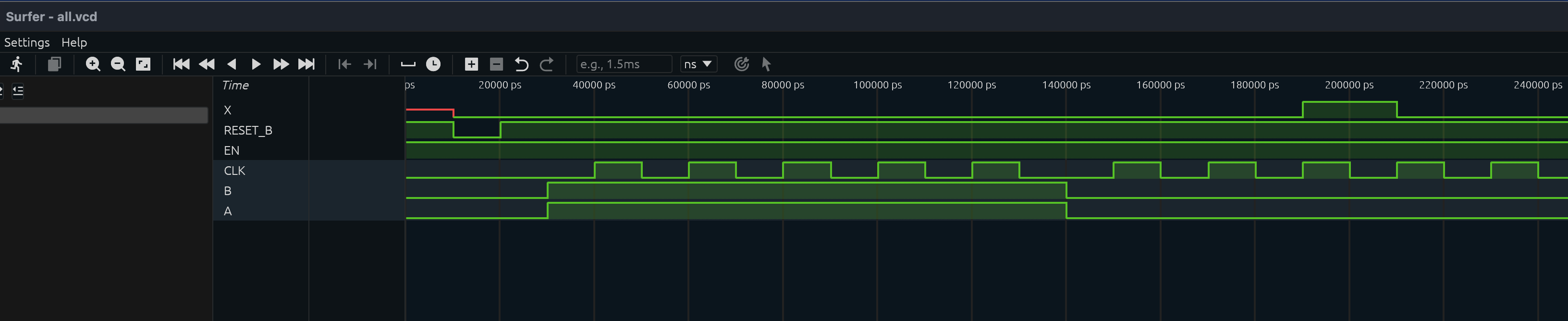
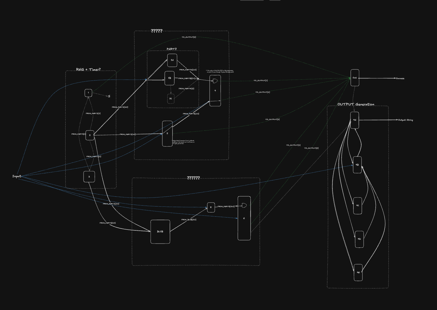
Grouping components into sub-blocks revealed that a 120-clock signal generator fed the main circuit, matching expected timing waveforms.
Uncovering secret output states
Fixing an unasserted reset pin enabled the full simulation, revealing hidden built-in messages like 'EMPTY SKY' for all zeros and 'BIG BANG' for all ones.
Reversing time with recurrence relations
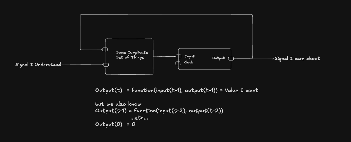
Brute-forcing a 120-bit input space was impossible, so desired target output signals were rewritten backwards as recurrence relations across time steps.
“So then if I take one step back in time I can re-write the desired output as a functions of the previous step.”
Generating Verilog with spreadsheets
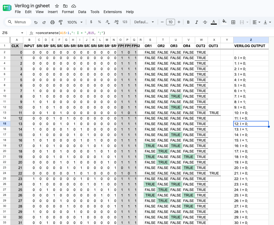
Google Sheets acted as an ad-hoc constraint solver, manually toggling bit values across clock cycles to generate working Verilog test code.
“Yes, that’s a spreadsheet that I used to write verilog that I then fed in to my simulated circuit.”
Unleashing the Z3 solver
Integrating Microsoft's Z3 SMT constraint solver allowed automated evaluation of thousands of backward wire rules in fractions of a second.
“I was able to give it thousands of constraints in the end and it would find solutions in the blink of an eye.”
Solving thousands of constraints
Combining all required wire state rules into one unified Z3 script computed the exact 120-bit input vector required for success.
“I now combined all of my constraints in to a single giant script and set about squashing the bugs.”
Unlocking the final secret flag
Executing the solver's calculated input sequence through the Verilog simulator generated the final winning output message: (* TWO STARS *).
“I loaded it in to my simulator, run it, and there it is. The answer - (* TWO STARS *)”
The big picture
When forward brute-forcing complex logic systems is impossible, converting hardware clock cycles into backward recurrence relations and feeding them to an SMT constraint solver can compute exact secret inputs.